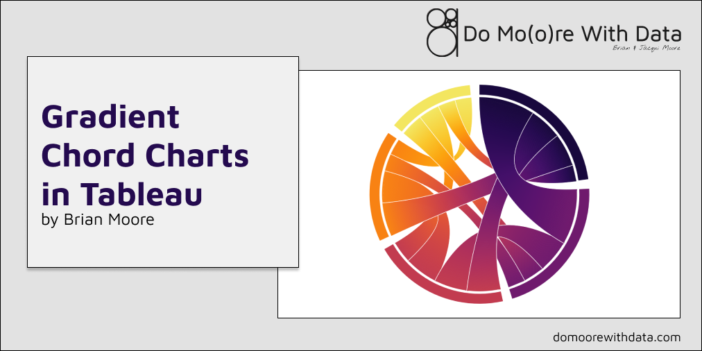
Chord charts are a great way to display and quantify relationships between entities, but there are some limitations. Recently, I built a series of chord charts to show which actors have appeared together in films, and how often. Once I had built out the charts and attempted to add some color, I hit a wall. In some cases, when building these relationship diagrams, there is a logical directional flow to the relationship. Something moves from Entity 1 (Source) to Entity 2 (Target). In those cases, its easy to assign meaningful color to the chart. You can assign it by Source if you want to highlight where things are flowing from, or you can assign it by Target if you want to highlight where things are flowing to. But what if there is no flow to the relationship? How do you assign color then?
This roadblock got me thinking. If I want to add a unique color to each Entity in my chart, and there is no directional flow, then the color of the chord should be a blend of the two colors. Or better yet, it should transition from one color to the other. I have seen others do some really cool stuff with applying gradients to “solid” chart types. Ken Flerlage has an excellent post here about applying gradients to Bar Charts and Area Charts. There’s another great post from Ivett Kovacs about gradients here. Some different techniques, but the foundation is the same. If you want to apply a gradient to an otherwise “solid” chart, use a series of thin lines to “color in” the chart. So that’s exactly what I did.
I’ll warn you ahead of time, this is going to be a long post. But if you’re just interested in building one of these charts, and not so much in how to build it, I’ve got some templates for you to use. Just follow the instructions in the “Setting Up Your Data Source” section below, and swap out the data source in the template workbook. You can download the template here, and download the sample data here.
Setting Up Your Data Source
In the sample data (link above), there are two tabs; one for our data, and one for densification. You do not need to make any changes to the Densification table, but I’ll talk through the setup as we build each section of this chart. In the Base Data, you should only update the first four columns and not the calculated fields (red text) in the next five columns. Here is a quick explanation of each field and what it represents
From_ID: Unique Identifier for each Source entity. This should be a sequential number starting at 1 and ending at however many entities you have in your data. For each entity, you may have multiple rows, one for each relationship, but they should all have the same From_ID.
From_Name: A display name for each Source entity.
To_Name: A display name for the other entity in the relationship, or the “Target”.
Value: The measure being displayed. In the sample data, this value field represents the number of movies that the two actors appeared in together.
The following fields should not be changed. They will update automatically based on the first 4 columns, but here is a quick description of what they are calculating.
To_ID: This is a lookup to get the correct ID for the Target entity
From_Total: This is a sum of the Value field for each Source entity
From_Run_Total: This is a running total of the Value field
Unique_Relationship: This is a unique identifier for the relationship
Unique_Relationship_Order: This is used to identify the first and second occurrence of each Unique_Relationship (there will be two rows for each relationship, one where Actor 1 is the Source and Actor 2 is the Target, and one where Actor 2 is the Source and Actor 1 is the Target).
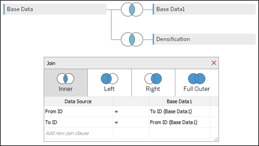
If you are building these charts from scratch, I would still recommend downloading the template to see how the Data Source is set up. In order to get the running total value for the Target, or the end of each chord, we are doing a self-join in the Physical Layer on the Base Data table (see below for join conditions). Then, we are re-naming the [From_Run_Total] field from the right side of that join (Base Data1) to [To_Run_Total]. And then we are joining to the Densification table using a join calculation (value of 1 on each side). Here is what the joins look like in our data source.
Building the Chart
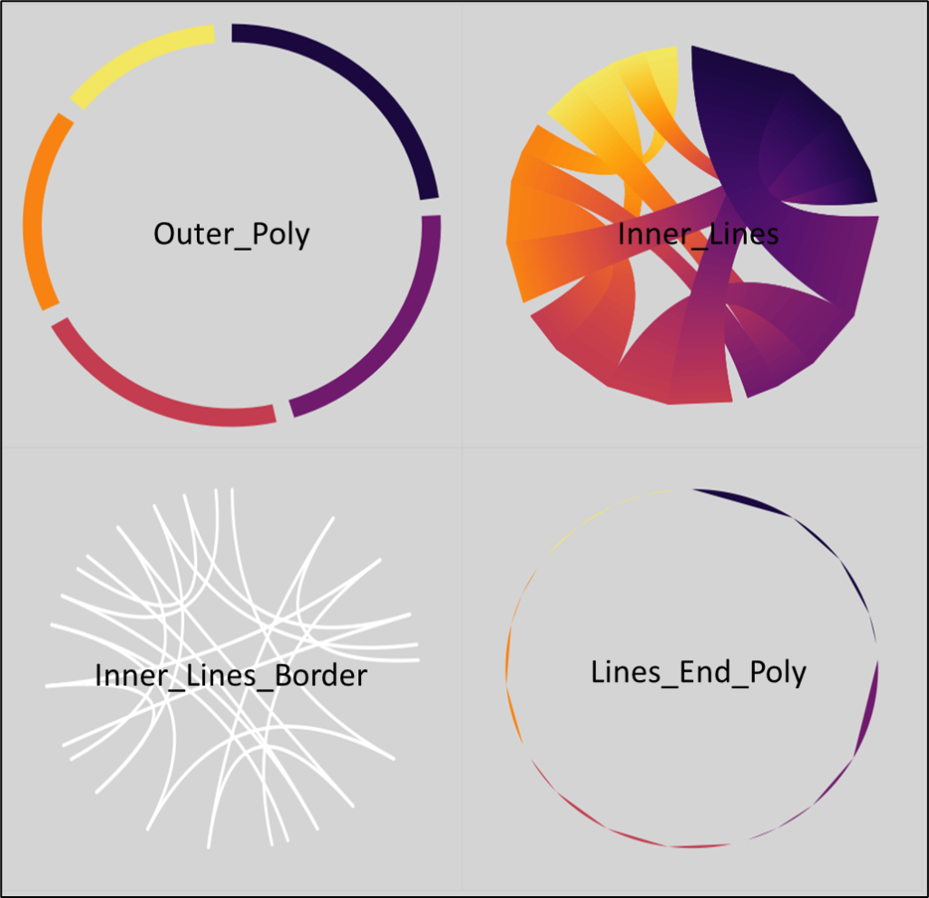
This chart is actually comprised of 4 different sections, identified by the ShapeType field in the densification table. There are the outer polygons (Outer_Poly), the gradient chords (Inner_Lines), the borders for the gradient chords (Inner_Lines_Border), and a small rounded polygon on the end of each chord (Lines_End_Poly) to fill the gap between the chords and the outer polygons.
Before we start working on any of these individual sections, there are a number of calculations that we are going to need for all of them.
First, let’s create a parameter that will let us control the spacing between each of the outer polygons. Call this parameter [Section Spacing], set the data type to Float, and set the value very low, around .01. Once you have the chart built you can set this higher for more spacing, or lower for less spacing.
Now let’s use that parameter, along with the Max of our running total field from the data source (which represents the grand total of the [Value] field), to calculate the width of our spacing between polygons. We’ll call this [Section Spacing Width]
Section Spacing Width = [Section Spacing]*{MAX([From Run Total])}
Now we need an adjusted grand total that accounts for all of the spaces as well. We’ll call this [Max Run Total – Adj] and it will be our grand total plus the number of spaces * the width of the spaces.
Max Run Total – Adj = {MAX([From Run Total])+MAX([From ID]*[Section Spacing Width])}
Next, we want to calculate the position around the circle where each of our sections, or entities, will start. We’ll do this by subtracting the [Value] field from the running total, adding the spacing for all previous sections, and then dividing that by our adjusted grand total. Call this field [Section_Start].
Section_Start = { FIXED [From ID] : MIN(([From Run Total]-[Value]) + (([From ID]-1)*[Section Spacing Width]))} / [Max Run Total – Adj]
Now we need to do the same thing to calculate the position around the circle where each section ends. The only difference between this and the previous calc, is that we are going to use the running total without subtracting the value. Call this field [Section_End]
Section_End = { FIXED [From ID] : MAX([From Run Total] + (([From ID]-1)*[Section Spacing Width]))} / [Max Run Total – Adj]
Now for an easy one. Let’s calculate the width of each section by subtracting the [Section_Start] from the [Section_End]. Call this [Section_Width].
Section_Width = [Section_End]-[Section_Start]
Next, we need to do the same thing to get the start and end positions for each of the “sub-sections”, or each of the entity’s relationships. The calculations are almost identical, the only difference is that we are fixing the Level of Detail calculations on [From_ID] and [To_ID], instead of just [From_ID]. Call these calculations [From_SubSection_Start] and [From_SubSection_End].
From_SubSection_Start = { FIXED [From ID],[To ID] : MIN(([From Run Total]-[Value]) + (([From ID]-1)*[Section Spacing Width]))} / [Max Run Total – Adj]
From_SubSection_End = { FIXED [From ID],[To ID] : MAX([From Run Total] + (([From ID]-1)*[Section Spacing Width]))} / [Max Run Total – Adj]
And just like before, we’ll create a simple calculation to get the “width” of these sub-sections. Call this calculation [SubSection_Width].
SubSection_Width = [From_SubSection_End]-[From_SubSection_Start]
Next, we need to do the same thing, but need to calculate the start and end position for the other end, or Target, of each relationship. The calculations are the same as above except we’ll use the [To_Run_Total] instead of [From_Run_Total] and [To_ID] instead of [From_ID]. Call these calculations [To_SubSection_Start] and [To_SubSection_End].
To_SubSection_Start = { FIXED [From ID],[To ID] : MIN(([To Run Total]-[Value]) + (([To ID]-1)*[Section Spacing Width]))} / [Max Run Total – Adj]
To_SubSection_End = { FIXED [From ID],[To ID] : MAX([To Run Total] + (([To ID]-1)*[Section Spacing Width]))} / [Max Run Total – Adj]
And finally, we need a simple calculation to get the total number of points for each of our shape types. Call this calculation [Max Point].
Max Point = { FIXED [Shape Type] : MAX([Points])}
Densification
Before we move on, let’s take a look at our densification table. In this table, we have 5 fields.
Shapetype: Corresponds to the 4 sections of the chart mentioned previously.
Points: Used, along with Side, to calculate the positions of every point, in every element of the chart.
Order: Used on Path to tell Tableau how to connect our Points.
Side: Used to differentiate between the interior and exterior “lines” for the outer polygons and chords.
Line ID: Used on Detail to segment our lines appropriately. For all sections of the chart, other than the Inner_Lines, this value will be 1, since we want one continuous line for the polygons, and for the borders of the chords. For the Inner_Lines, we have values from 1 to 1,000, so we can “color” our chart with up to 1,000 lines per chord.
These fields are used in slightly different ways in each section of the chart, so we’ll talk about them more as we start building.
Building the Outer Polygons
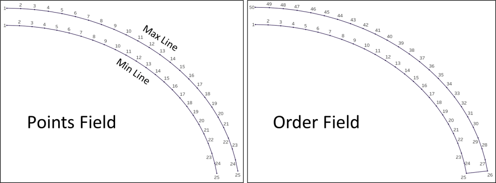
First, let’s take another quick look at our densification table. For the outer polygons, identified by Shapetype=Outer_Poly, we have a total of 50 records. The Order field, used to tell Tableau how to connect the points, is a sequential number from 1 to 50. Then there is the Points field, which is used to calculate the position of each point around the circle. This number goes from 1 to 25, where the Side field = Min, and repeats where the Side field = Max. This will allow us to draw two parallel lines (Min and Max), and then connect them together to create those outer polygons. And lastly, the Line ID has a value of 1 because we are “drawing” one continuous “line” for each of these polygons. Clear as mud right? Here’s a quick illustration to help visualize how these fields function together.
Before we start building the calculations for this section, we need a few parameters. The first is just going to be a generic value for the radius of our circle. The second, is going to determine the thickness of these outer polygons.
Create a parameter called [Radius], set the data type to Float and set the Current value to 10. This can be any number you want, it doesn’t really matter, we just need something to determine the size of our chart.
Next, create a parameter called [Outer_Poly_Thickness], set the data type to Float, and set the Current value to 1. You can play around with this number to get the thickness you want, but I would recommend setting it somewhere around 10% of the [Radius] value.
Now for our calculations. Going back to Part 1 of the Fun with Curves in Tableau Series, we know that we need 2 inputs to plot points around a circle. We need the distance of each point from the center of the circle, and we need the position of each point around the circle. Let’s start with the distance.
In the image from earlier in this section, we see that we need two lines that follow the same path, one for Min and one for Max. So these two lines will have different distances from the center. For the Min line, we’ll just use the [Radius] of our circle. For the Max line, we’ll use the [Radius] plus our [Outer_Poly_Thickness] parameter. Create a calculated field called [Outer_Poly_Distance].
Outer_Poly_Distance = IF [Side]=”Min” THEN [Radius] ELSE [Radius]+[Outer_Poly_Thickness] END
Next, we need to calculate the position of the points. Each of our polygons are going to be different lengths, depending on the [Value] field in our data source, so we need to calculate the spacing of each point (to evenly space 25 points along the two “lines”). Earlier, we calculated the start and end position for each of these polygons, and we’ll use those to calculate the spacing, or “width”, that each point covers. Create a calculated field called [Outer_Poly_Point_Width].
Outer_Poly_Point_Width = [Section_Width]/([Max Point]-1)
And now we’ll use that, along with the start position of each polygon, to calculate the position for each of our 25 points. Point 1 will be positioned at the start of the polygon, Point 25 will be positioned at the end of the polygon, and the remaining 23 points will be equally spaced between those two points. Call this calculation [Outer_Poly_Point_Position].
Outer_Poly_Point_Position = [Section_Start]+(([Points]-1)*[Outer_Poly_Point_Width])
Now we have the two inputs needed to calculate all of our points for these outer polygons. We just need to plug them into our X and Y calculations.
Outer_Poly_X = [Outer_Poly_Distance]* SIN(2*PI() * [Outer_Poly_Point_Position])
Outer_Poly_Y = [Outer_Poly_Distance]* COS(2*PI() * [Outer_Poly_Point_Position])
Let’s pause here and build a quick view to test out our calculations so far.
- Drag [ShapeType] to filter and filter on “Outer_Poly”
- Change Mark Type to Polygon
- Right click on [Outer_Poly_X], drag it to Columns, and when prompted, choose Outer_Poly_X without aggregation
- Right click on [Outer_Poly_Y], drag it to Rows, and when prompted, choose Outer_Poly_Y without aggregation
- Drag [From_ID] to color
- Right click on [Order], convert to Dimension, and then drag to Path
If all of the calculations are correct, your sheet should look something like this.
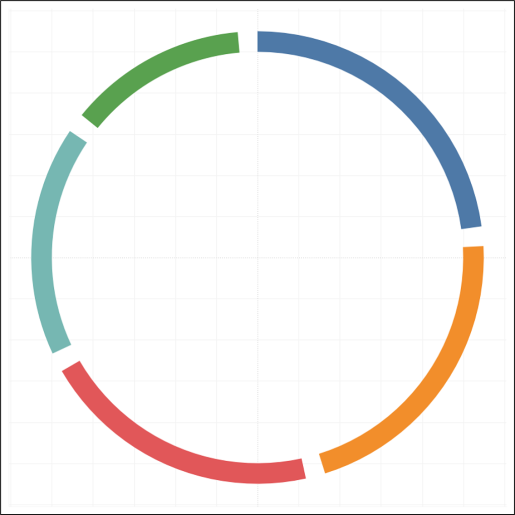
One section down, three more to go.
Building the Line End Polygons
Next, let’s build the small rounded polygons that are going to go at the end of each of our chords. The calculations will be pretty similar to the previous section. For those outer polygons, we essentially drew two curved lines that followed the same path, and then connected those lines by using the Polygon Mark Type, and using our [Order] field on Path. Now, we basically want to do the same thing, but with a few minor differences. Instead of drawing two lines, we only need to draw one. Tableau will automatically connect our first and last point, resulting in a small semi-circle. The other difference is that instead of drawing one polygon for each entity (actor in this example), we need to draw a polygon for each relationship.
To draw these polygons, we need the same exact 5 calculations as we did in the previous section, but with some modifications. To start, let’s build a parameter to control the spacing between these polygons, and the outer polygons. Call this parameter [Poly_Spacing], set the data type to Float, and set the current value to .25. Again, once the view is built, you can play with this parameter to get the spacing you want.
Next, we need to calculate the distance of our points from the center of the circle. We’ll do this by subtracting our [Poly_Spacing] value from the [Radius] . Call this calculation [Line_End_Poly_Distance].
Line_End_Poly_Distance = [Radius]-[Poly_Spacing]
Next, we need to calculate the position for our 25 points, just like we did in the previous section. The only difference here, is that instead of using the section start and section end, we’re going to use the sub-section start, and sub-section end, since we need to create these for each relationship. Call this calculation [Line_End_Poly_Point_Width].
Line_End_Poly_Point_Width = [SubSection_Width]/([Max Point]-1)
Using that, along with our Subsection start calculation, we can calculate the position of all 25 points for these polygons. Call this calculation [Line_End_Poly_Point_Position].
Line_End_Poly_Point_Position = [From_SubSection_Start]+(([Points]-1)*[Line_End_Poly_Point_Width])
And now we just need to plug these inputs into our X and Y calculations.
Line_End_Poly_X = [Line_End_Poly_Distance]* SIN(2*PI() * [Line_End_Poly_Point_Position])
Line_End_Poly_Y = [Line_End_Poly_Distance]* COS(2*PI() * [Line_End_Poly_Point_Position])
Once again, let’s pause to check our work.
- Drag [ShapeType] to filter and filter on “Line_End_Poly”
- Change Mark Type to Polygon
- Right click on [Outer_Poly_X], drag it to Columns, and when prompted, choose Outer_Poly_X without aggregation
- Right click on [Outer_Poly_Y], drag it to Rows, and when prompted, choose Outer_Poly_Y without aggregation
- Drag [From_ID] to Color
- Drag [To_ID] to Detail
- Right click on [Order], convert to Dimension, and then drag to Path
When complete, the line end polygons should look something like this.
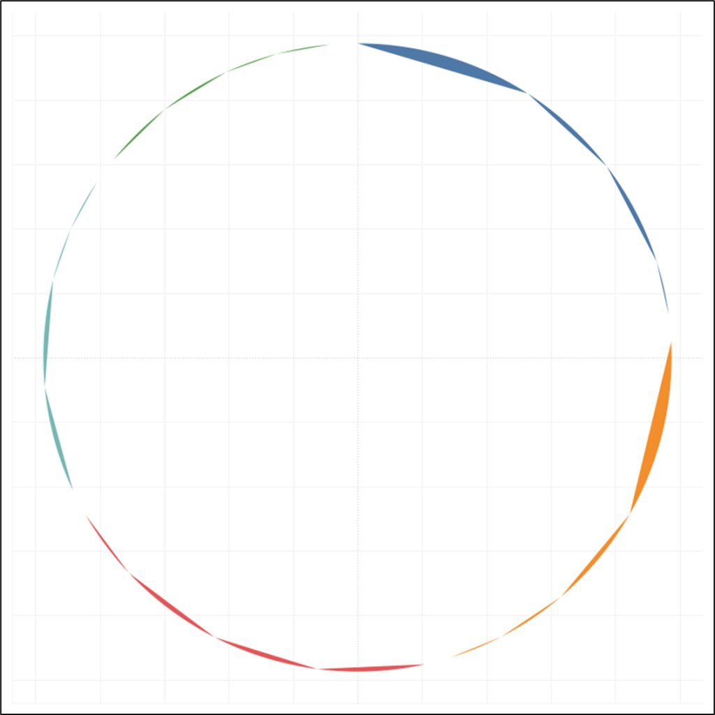
We’re halfway there! Kind of…
Building the Inner Line Borders
Now we need to build our chords. Let’s start with the borders since those are a little more straightforward, and will make the last section a little easier to understand.
Going back to Part 2 of the Fun with Curves in Tableau Series, we know that we need 3 sets of coordinates to create our bezier curves; one for the start of the line, one for the end of the line, and one for the mid-point. Since we’re building a chord chart, we’ll use 0,0, for the mid-point. So that just leaves the start and end of our lines.
As always, we’ll need 2 inputs to calculate these coordinates, the distance and position. The distance is easy. It’s going to be the same distance as our Line End Polygons, [Radius] – [Poly_Spacing]. The position is a little more tricky.
For each of our chords, we’re going to need 2 lines, one for the interior, or Min, line, and one for the exterior, or Max line.
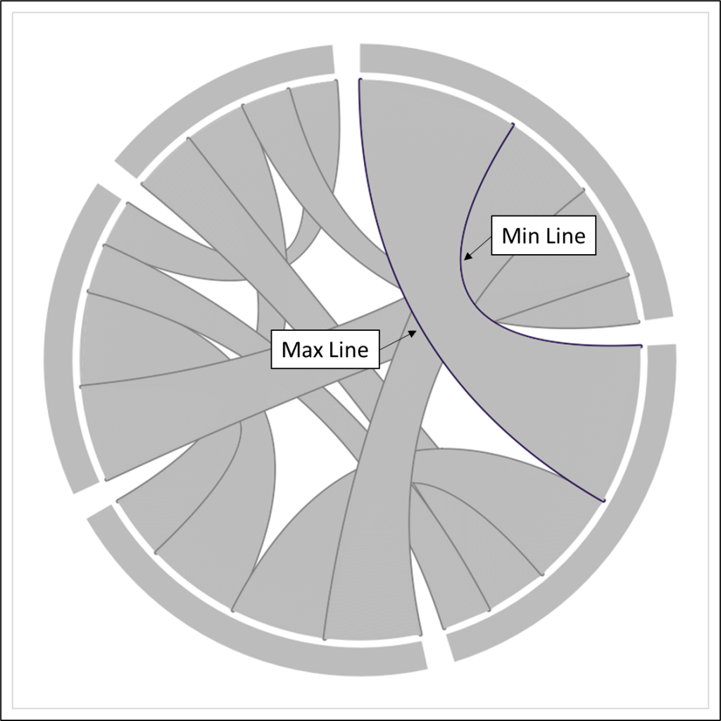
Notice the Min Line, starts at the end of the first chord, or sub-section, and then ends at the start of the target sub-section. The opposite is true for the Max Line. This line starts at the start of the first chord, and ends at the end of the target sub-section. We have already calculated the position for all of those sections, so we can plug those into our X and Y calcs to get our coordinates. We’ll need two sets of calculations, one for the starting coordinates and one for the ending coordinates.
Chord_X_Start = if [Side]=”Min” then ([Radius]-[Poly_Spacing])* SIN(2*PI() * [From_SubSection_End])
else ([Radius]-[Poly_Spacing])* SIN(2*PI() * [From_SubSection_Start])
END
Chord_Y_Start = if [Side]=”Min” then ([Radius]-[Poly_Spacing])* COS(2*PI() * [From_SubSection_End])
else ([Radius]-[Poly_Spacing])* COS(2*PI() * [From_SubSection_Start])
END
Chord_X_End = if [Side]=”Min” then ([Radius]-[Poly_Spacing])* SIN(2*PI() * [To_SubSection_Start])
else ([Radius]-[Poly_Spacing])* SIN(2*PI() * [To_SubSection_End])
END
Chord_Y_End = if [Side]=”Min” then ([Radius]-[Poly_Spacing])* COS(2*PI() * [To_SubSection_Start])
else ([Radius]-[Poly_Spacing])* COS(2*PI() * [To_SubSection_End])
END
These calculations may look complicated, but they’re all relatively simple. They are all using the same distance input (Radius – Poly Spacing), and then depending on if it’s the Min line or the Max line, and if it’s the Start or End of the line, we’re plugging in the appropriate position field (From_SubSection_Start, From_SubSection_End, To_SubSection_Start, and To_SubSection_End).
Those four calculations will give us the 2 remaining sets of coordinates needed to draw our bezier curves. So let’s plug all of our coordinates into the bezier X and Y calculations. But first, we need to calculate [T] to evenly space points along our lines.
T = ([Points]-1)/([Max Point]-1)
Chord_X = ((1-[T])^2*[Chord_X_Start] + 2*(1-[T])*[T]*0+[T]^2*[Chord_X_End])
Chord_Y = ((1-[T])^2*[Chord_Y_Start] + 2*(1-[T])*[T]*0+[T]^2*[Chord_Y_End])
Let’s pause again and make sure our calculations are working as expected.
- Drag [ShapeType] to filter and filter on “Inner_Lines_Border”
- Change Mark Type to Line
- Right click on [Chord_X], drag it to Columns, and when prompted, choose Chord_X without aggregation
- Right click on [Chord_Y], drag it to Rows, and when prompted, choose Chord_Y without aggregation
- Drag [From_ID] to Color
- Drag [To_ID] to Detail
- Drag [Line_ID] to Detail
- Right click on [Order], convert to Dimension, and then drag to Path
When finished, your bezier curves should look something like this. There should be two lines for each relationship in your data source.
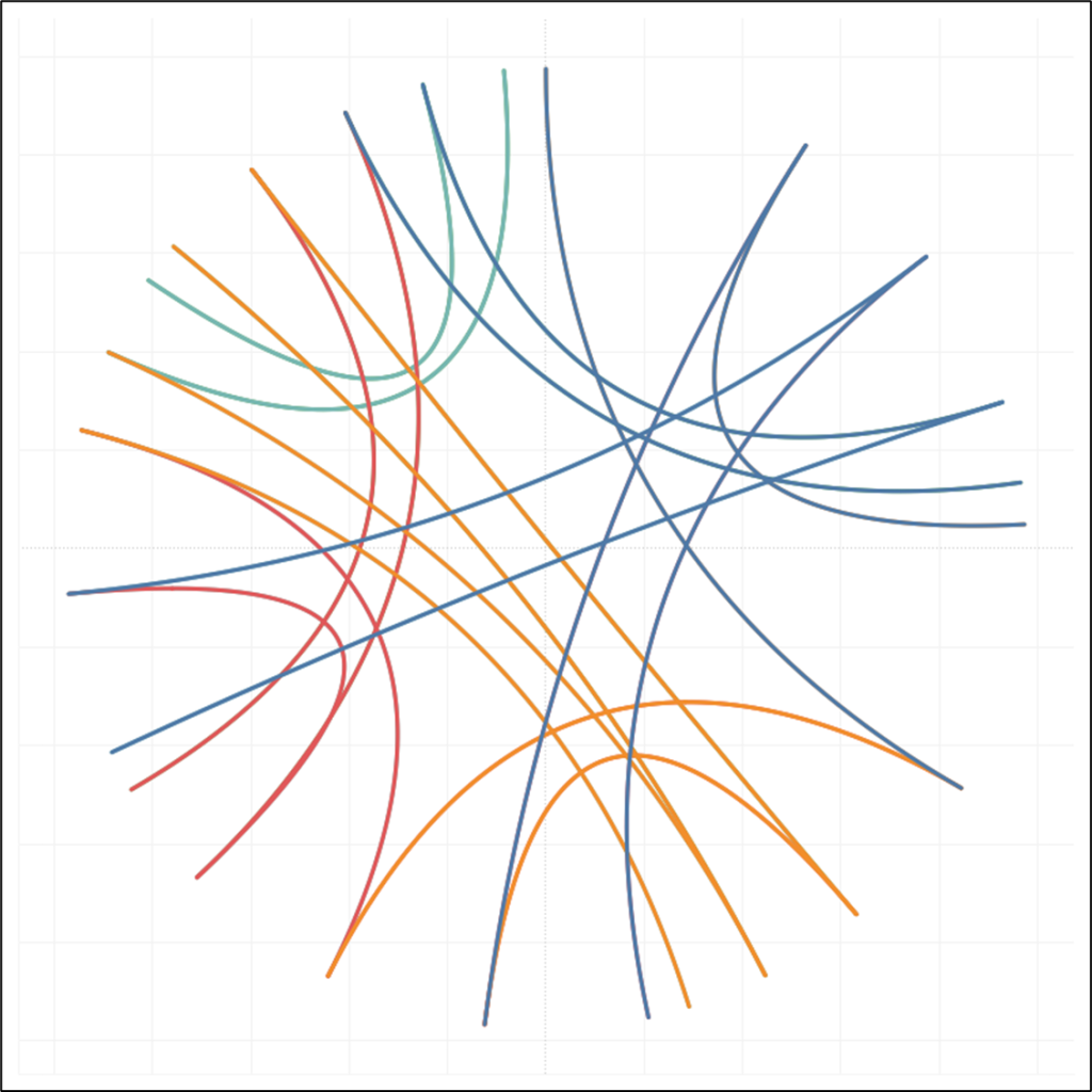
We’re getting close!
Building the Inner Lines
Here’s the fun part. This is the section that really makes this chart unique. And guess what…we already built all of the calculations needed to make this work. Go the sheet you built in the previous section, and change the filter from Inner_Lines_Border to Inner_Lines…I’ll wait. Pretty cool right? These may look like polygons, but really, each of these chords is being “colored” with 1,000 individual lines. Go ahead and click on a few to see for yourself.
This is what one of those chords would look like if we had used 50 lines instead of 1,000.
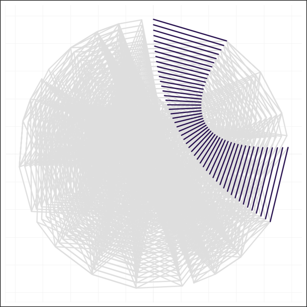
So how does this work? How were we we able to use the same exact calculations for the chord borders, and these inner lines, when all we did was change a filter? It’s all in how we set up the densification table.
For both of these sections, we used the [Points] field in the same way…to calculate the position of each point along the chords. The [Line ID] and [Order] fields are where the magic happens.
Let’s look at the chord borders first.
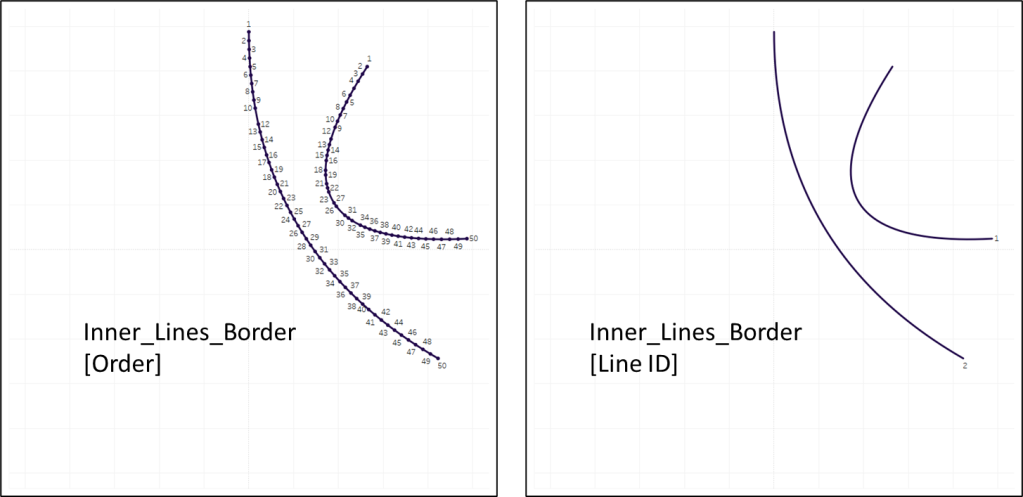
For these lines, the [Order] field has sequential numbers from 1 to 50, and the [Line ID] field has just two values, 1 and 2. With [Line ID] on Detail, and [Order] on Path, this will draw 2 curved lines.
Now look at the inner lines.
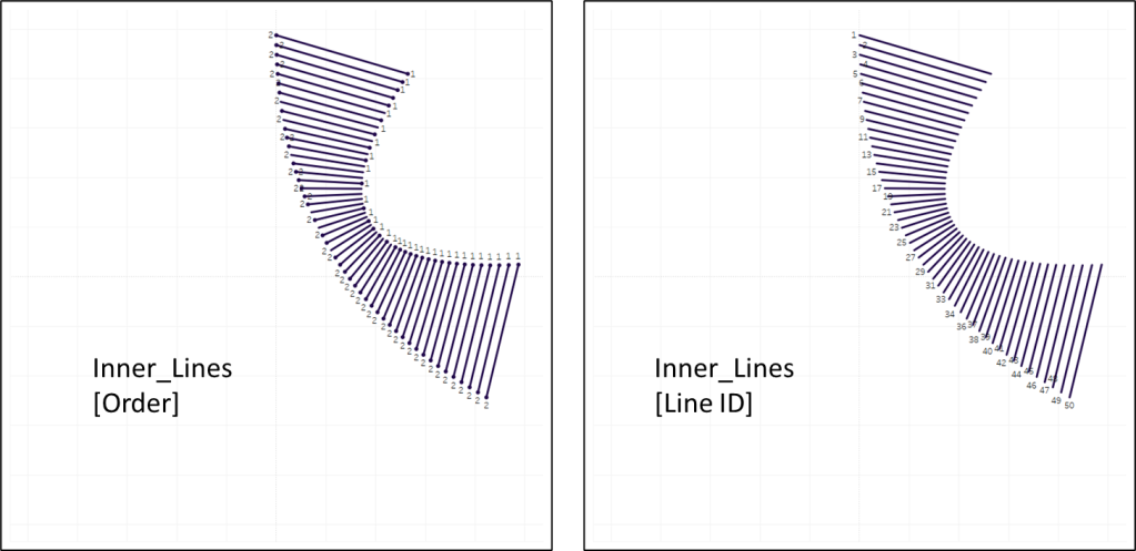
For these lines, the [Order] field has just two values, 1 and 2, and the [Line ID] field has sequential numbers from 1 to 50 (up to 1,000 in the final chart). In this case, when you put [Line ID] on Detail, and [Order] on Path, it will draw 50 straight lines.
So using the same exact calculations, but getting a little creative with our data source, we can draw both the borders of our chords, and “color” them in. Now let’s bring all of these sections together. We’re almost done!
Building the Final Chart
So now we have all of the calculations done for the four sections of our chart. Time to bring them together. In this viz we have two different Mark Types that we are trying to use together; Polygons and Lines. So we’ll need to use a dual axis and create a calculation for each mark type. All of our sections will share the same Y calculation, but we’ll have an X calculation for the polygon sections, and an X calculation for the line sections. These will all be simple case statements to use the appropriate X and Y values for each section of the chart.
Final_X_Line
CASE [Shape Type]
WHEN “Inner_Lines” then [Chord_X]
WHEN “Inner_Lines_Border” then [Chord_X]
END
Final_X_Poly
CASE [Shape Type]
WHEN “Outer_Poly” then [Outer_Poly_X]
WHEN “Line_End_Poly” then [Line_End_Poly_X]
END
Final_Y
CASE [Shape Type]
WHEN “Inner_Lines” then [Chord_Y]
WHEN “Inner_Lines_Border” then [Chord_Y]
WHEN “Outer_Poly” then [Outer_Poly_Y]
WHEN “Line_End_Poly” then [Line_End_Poly_Y]
END
Now to build our view. Let’s start with the Line sections.
- Change Mark Type to Line
- Right click on [Final_X_Line], drag it to Columns, and when prompted, choose Final_X_Line without aggregation
- Right click on [Final_Y], drag it to Rows, and when prompted, choose Final_Y without aggregation
- Drag [From ID] to Detail
- Drag [To ID] to Detail
- Drag [ShapeType] to Detail
- Drag [Line ID] to Detail
- Drag [Order] to Path
When this part is complete, your chart should look something like this.
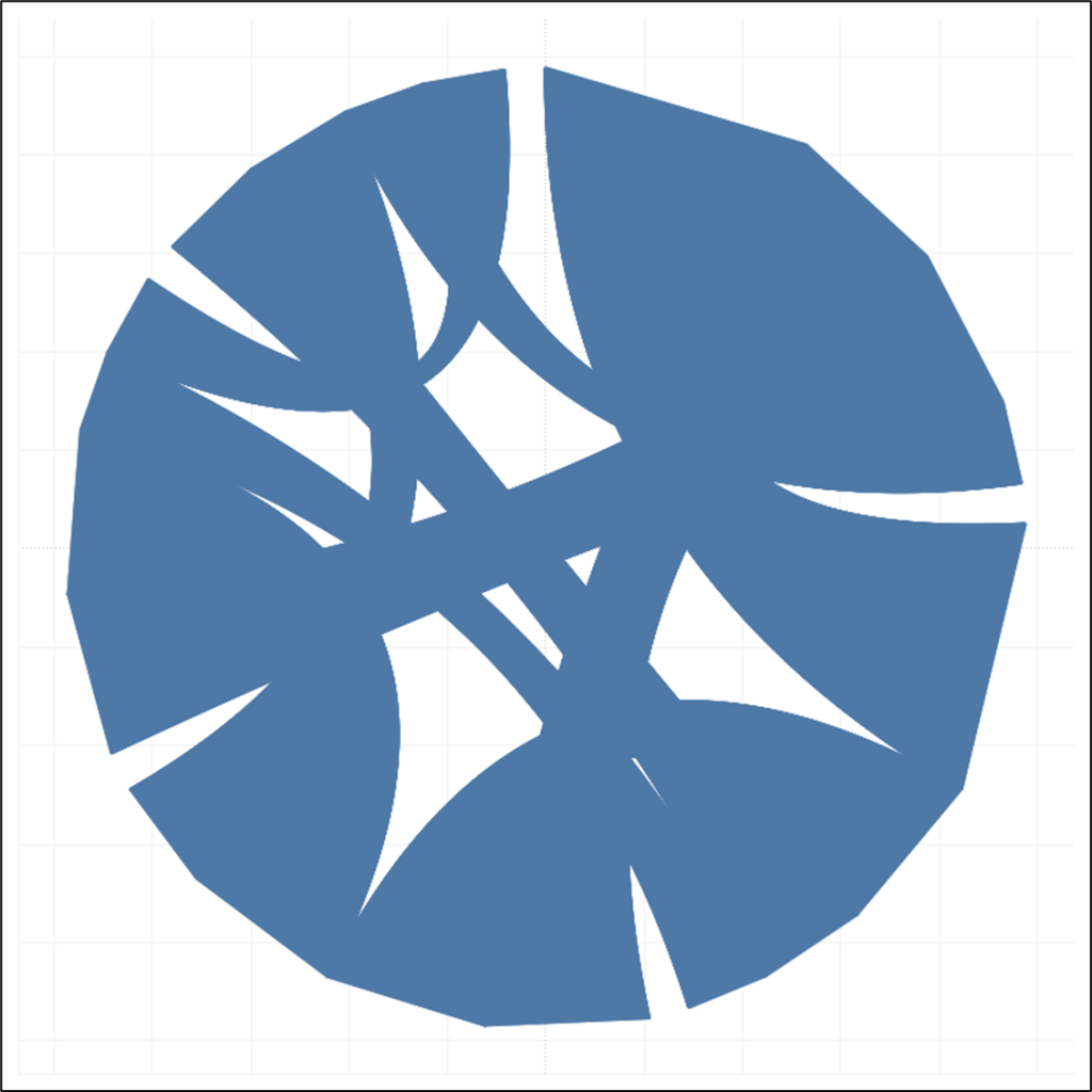
Now, let’s add our polygons.
- Right click on [Final_X_Poly], drag it to the right of [Final_X_Line] on the Columns shelf, and when prompted, choose Final_X_Poly without aggregation
- Right click on the green [Final_X_Poly] pill on the columns shelf and select “Dual Axis”
- Right click on one of the axes, and select “Synchronize Axis”
- On the Marks Card, go to the Final_X_Poly card and change the Mark Type to Polygon
- Remove the [To ID] field from Detail
- Remove the [Line ID] field from Detail
- Drag the [Unique Relationship] field to Detail
At this point, your chart should look something like this.

Woohoo, our chart is built! Before we start fine tuning our design, there are a few filters we should add. All of these will improve performance, but one of them is needed to accurately color our chart.
First, for our outer polygons, there are actually a number of identical polygons stacked on top of each other. The way our data is set up, it’s creating one of these polygons for each relationship for each entity. But we only want one polygon per entity. This will not only improve performance, but also fix some weird display issues that happen on Tableau Public. It doesn’t happen all the time, but sometimes when you have multiple identical polygons stacked on top of each other, the curved lines end up looking jagged and weird. So this will help fix that. This filter will include anything that’s not an outer polygon, and only the first outer polygon for each entity. We’ll call this [Single_Outer_Poly_Filter].
Single_Outer_Poly_Filter = [Shape Type]!=”Outer_Poly” or ([Shape Type]=”Outer_Poly” and [To ID]={ FIXED [From ID] : MIN([To ID])})
Drag that to the Filter shelf and filter on True.
This next calculation helps with performance and also ensures an accurate color calculation in the next section. For each of our chords, as it stands now, there are actually two sets of lines stacked on top of each other. That’s because each unique relationship has two rows in our source data (one where Actor 1 is the Source and Actor 2 is the Target, and one where Actor 2 is the Source and Actor 1 is the Target). This calculation will keep all of the records for our two polygon sections, but for the line sections, it will only keep the first occurence of each relationship. Call it [Unique_Relationship_Filter].
Unique_Relationship_Filter = CONTAINS([Shape Type],”Poly”) or (not CONTAINS([Shape Type],”Poly”) and [Unique Relationship Order]=1)
Drag that to the Filter shelf and filter on True.
This last one is purely for performance and is completely optional. Depending on how large this chart will be in your viz, you may not need 1,000 lines to color the chords. You can use a parameter and a calculated field to set the number of lines you want to use. First, create a parameter called [Gradient Lines], set the data type to float, set the max value to 1,000, and set the current value to about 750. Then create a simple calc called [Gradient_Line_Filter].
Gradient_Line_Filter = [Points]<=[Gradient Lines]
Drag this field to the Filter shelf and filter on True. Then, right click on the blue pill, and select “Add to Context”.
Alright, now we’re ready to move on to Design!
Adding Color to the Chart
This part took me a little while to figure out. The goal is to be able to have a unique color for each of the entities, and then have the chord between them, transition from one of the entity’s colors, to the other. We have our [From_ID] field that is a sequential number for each entity, so that’s what we’ll use to color our polygons.
To color our chord borders, we’re going to use a parameter with a value lower than our first [From ID], and I’ll talk more about this a little later on. For now, create a parameter called [Color Range Start], set the data type to Float, and set the current value to .5.
To color the gradient lines, we’ll need a few calculations. The first thing we need to do, is calculate an evenly spaced value between the ID for the Source entity and the ID for the Target entity. For example, if we have a chord going from entity 1 to entity 2, we’ll take the difference of those and divide by the number of lines (1,000). Same thing if we have a chord going from entity 1 to entity 5. Let’s create that calc and call it [Color Step Size].
Color Step Size = ABS([From ID]-[To ID])/([Max Point]-1)
Now we’ll multiply that value by the [Points] field and add it to our [From ID] field to get evenly spaced values between the Source ID and the Target ID. Call this [Step Color Num].
Step Color Num = [From ID] + (([Points]-1)*[Color Step Size])
And finally, a simple case statement to use the [Step Color Num] value for the inner lines, the [From ID] value for the polygons, and the [Color Range Start] value for the chord borders. Call this [Color].
Color
CASE [Shape Type]
WHEN “Inner_Lines” then [Step Color Num]
WHEN “Line_End_Poly” then [From ID]
WHEN “Outer_Poly” then [From ID]
WHEN “Inner_Lines_Border” then [Color Range Start]
END
Now, on the Marks Card, click on the “All” card. Then, right click on the [Color] field, drag that onto Color, and when prompted, choose Color without aggregation. Notice something kind of funky happens when you add the Color.

Our Border Lines are rising to the top and crossing over all of the Inner Lines, which is not what we want. The reason this is happening, is that Tableau uses the order of fields on the Marks Card to sort. When we added [Color], it moved to the top of the list of fields on the Marks Card, so that is the first thing being used to sort. Since our Borders all currently have the lowest value of any mark (based on the parameter we created earlier, it should be .5), those lines are coming to the top.
To fix that, on the Marks Card, on the Final_X_Line card, drag the [Color] field all the way to the bottom. The order of the fields on the Marks Card should be as follows to get the correct sorting.
- From ID
- To ID
- Shape Type
- Line ID
- Order
- Color
Now your chart should look something like this.

It’s starting to come together!
Picking the Right Colors
You could use any of the sequential palettes available in Tableau, and they would work just fine. But for my viz, I wanted unique colors for each of the entities, not different shades of the same color. The palette I ended up using is called “Inferno”. You can create any custom palette you would like, but you want to make sure you pick a palette that is “Perceptually Uniform”. There is a lot behind these palettes, but basically it means that each color in your palette is close to the next color, and the amount of change between one color and the next is consistent throughout the entire palette. Here are some great examples of Perceptually Uniform color scales.
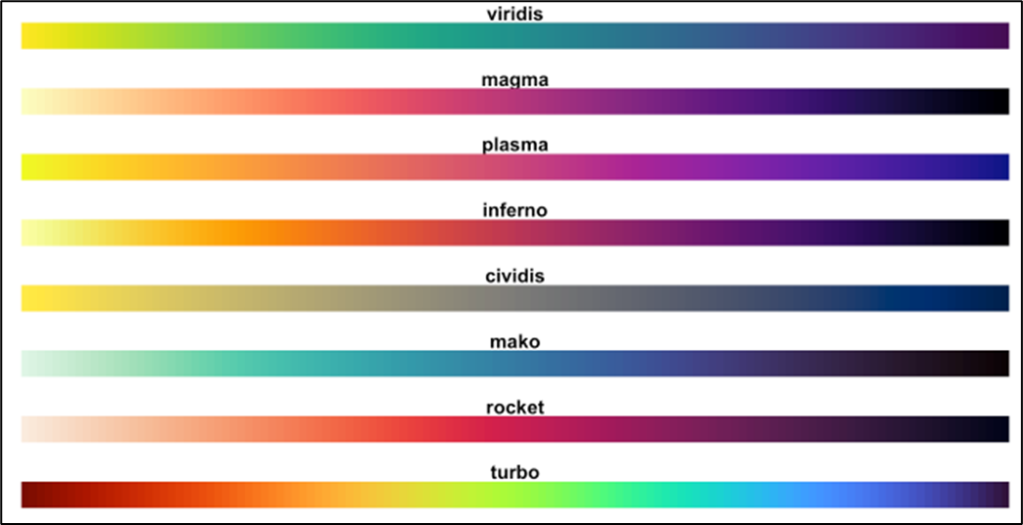
Here is the color palette that I used, and if you’re not sure how to add custom color palettes to Tableau Desktop, here’s an article from the Tableau Knowledge Base.
<color-palette custom=’true’ name=’Inferno’ type=’ordered-sequential’>
<color>#F3E660</color>
<color>#FAC72C</color>
<color>#FCA50F</color>
<color>#F98511</color>
<color>#EE6925</color>
<color>#DD513A</color>
<color>#C73E4C</color>
<color>#AE2F5C</color>
<color>#932667</color>
<color>#781C6D</color>
<color>#5C136E</color>
<color>#420F68</color>
<color>#24094F</color>
<color>#090625</color>
<color>#FFFFFF</color>
</color-palette>
Just a few things to keep in mind when building your palette. I would recommend ordering them in your preferences file from lightest to darkest. Also, on the very last line, add a line for White (#FFFFFF). This is what is used for the chord border color. Also, make sure that you set the type=sequential.
Once you add your custom palette, go ahead and select it from the Color options on the Mark Card. If you ordered your colors from lightest to darkest, you’ll also want to check the “Reversed” box in the color options.
Now that I’ve added my custom palette and applied it to the viz, this is what it looks like.
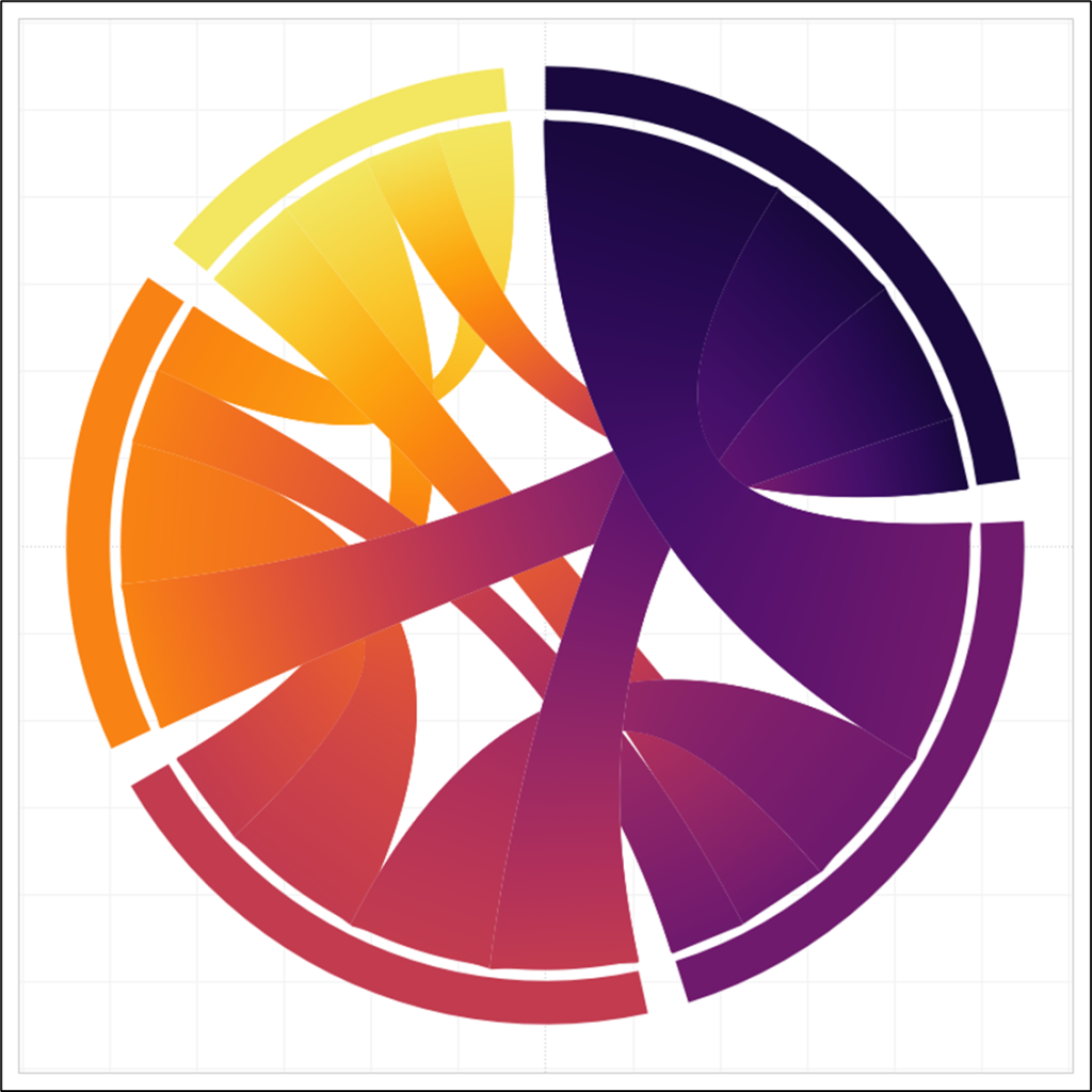
Just one more note about color. We had built that [Color Range Start] parameter to select a value that can be used for coloring the borders. In my sample data, I only had 5 entities, so the largest value in my [Color] field is 5. When I use .5 in that parameter, it gives me the full color range from my palette, and a white border. If you have more or less entities, that might not be the case. You may need to play with this parameter a bit to make it work correctly for your chart.
If you pick a number that is too low, you will not get the full color range from your palette. This is what it looks like if I set that value to -1.

On the other side of that, if you pick a number that is too high, the white from your palette will start to “bleed” into your chart. This is what it looks like if I set the value to .9
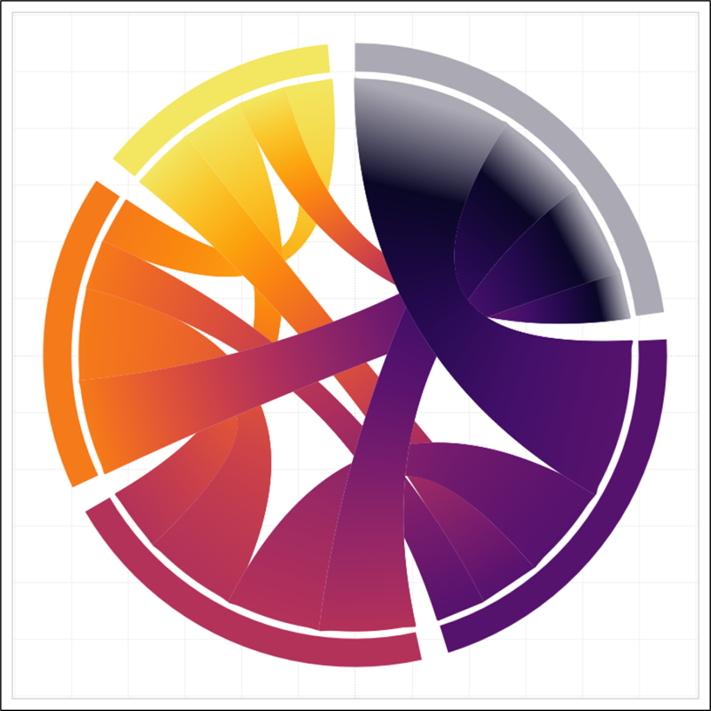
It’s not an exact science, so just play with that parameter until you have a white border and your full color range. If you don’t have the full color range, increase that parameter value. If the white is bleeding into your chart, decrease that value.
Finishing Touches
We are almost done! Just a few more steps that I would recommend. First, hide the null indicator in the bottom right of the chart, by right clicking on it and selecting “Hide Indicator”. Then clean up your borders and grid lines, and last, but definitely not least, I would recommend creating a calculated field to determine the thickness of your lines. For the gradient lines, we want a very thin line, but for the borders, it should be a little bit thicker. Create a calculated field called [Line Size].
Line Size = If [Shape Type]=”Inner_Lines_Border” then 2 else 1 END
Then, on the Marks Card, on the Final_X_Line card, right click on the [Line Size] field, drag it to Size, and then select Line Size without aggregation when prompted. Then, similar to what we did with Color, drag that field all the way down to the bottom on the Marks card, below [Color]. Again, you can play with these to get the look that you want. Double click on the Size Legend, and play with the slider. This is how mine are set.
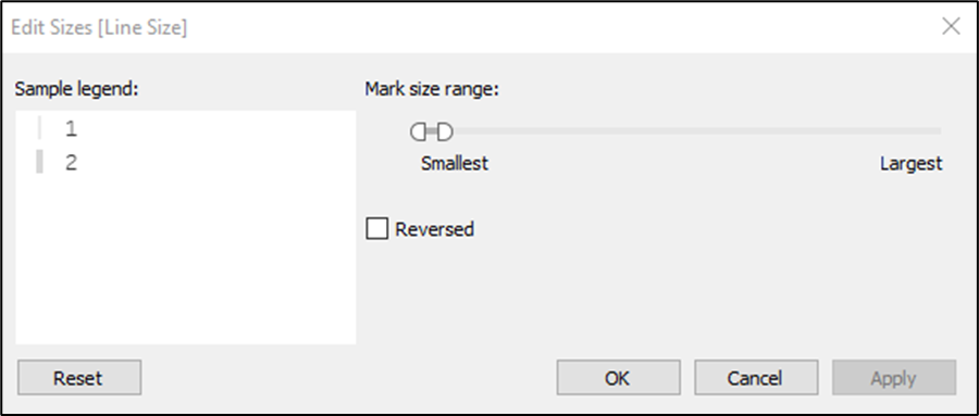
And that’s it! We are done! If you have made it this far, please let me know on Twitter or LinkedIn. This was the most complicated topic we’ve covered so far, and I would love to get your thoughts, and to see what you came up with. As always, thanks for reading, and check back soon for more fun Tableau tutorials!

